slider-crank mechanism
mechanics
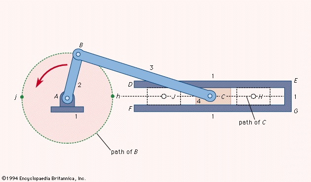 arrangement of mechanical parts designed to convert straight-line motion to rotary motion, as in a reciprocating piston engine, or to convert rotary motion to straight-line motion, as in a reciprocating piston pump. The basic nature of the mechanism and the relative motion of the parts can best be described with the aid of the accompanying figure-->, in which the moving parts are lightly shaded. The darkly shaded part 1, the fixed frame or block of the pump or engine, contains a cylinder, depicted in cross section by its walls DE and FG, in which the piston, part 4, slides back and forth. The small circle at A represents the main crankshaft bearing, which is also in part 1. The crankshaft, part 2, is shown as a straight member extending from the main bearing at A to the crankpin bearing at B, which connects it to the connecting rod, part 3. The connecting rod is shown as a straight member extending from the crankpin bearing at B to the wristpin bearing at C, which connects it to the piston, part 4, which is shown as a rectangle. The three bearings shown as circles at A, B, and C permit the connected members to rotate freely with respect to one another. The path of B is a circle of radius AB; when B is at point h the piston will be in position H, and when B is at point j the piston will be in position J. On a gasoline engine, the head end of the cylinder (where the explosion of the gasoline-air mixture takes place) is at EG; the pressure produced by the explosion will push the piston from position H to position J; return motion from J to H will require the rotational energy of a flywheel attached to the crankshaft and rotating about a bearing collinear with bearing A. On a reciprocating piston pump the crankshaft would be driven by a motor.
- Lydd
- Lydgate, John
- Lydia
- Lydia Barrington Darragh
- Lydia Cabrera
- Lydia E. Pinkham
- Lydia Folger Fowler
- Lydia Maria Adams DeWitt
- Lydia Maria Child
- Lydia Moss Bradley
- Lydian language
- Lydian mode
- lye
- Lyell, Mount
- Lyell, Sir Charles, Baronet
- lygaeid bug
- Lyly, John
- Lyman Abbott
- Lyman Beecher
- Lyman, Jr. Spitzer
- Lyman (Louis) Lemnitzer
- Lyman Reed Blake
- Lyman Spitzer, Jr.
- Lyman Trumbull
- Lyme disease