electric generator
instrument
Introduction
also called dynamo,
any machine that converts mechanical energy to electricity for transmission and distribution over power lines to domestic, commercial, and industrial customers. Generators also produce the electrical power required for automobiles, aircraft, ships, and trains.
The mechanical power for an electric generator is usually obtained from a rotating shaft and is equal to the shaft torque multiplied by the rotational, or angular, velocity. The mechanical power may come from a number of sources: hydraulic turbines (turbine) at dams or waterfalls; wind turbines; steam turbines using steam produced with heat from the combustion of fossil fuels or from nuclear fission; gas turbines burning gas directly in the turbine; or gasoline and diesel engines. The construction and the speed of the generator may vary considerably depending on the characteristics of the mechanical prime mover.
Nearly all generators used to supply electric power networks generate alternating current, which reverses polarity at a fixed frequency (usually 50 or 60 cycles, or double reversals, per second). Since a number of generators are connected into a power network, they must operate at the same frequency for simultaneous generation. They are therefore known as synchronous generators or, in some contexts, alternators.
Synchronous generators
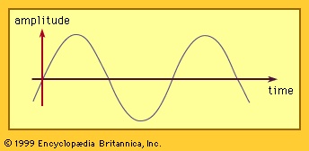 A major reason for selecting alternating current for power networks (alternator) is that its continual variation with time allows the use of transformers. These devices convert electrical power at whatever voltage and current it is generated to high voltage and low current for long-distance transmission and then transform it down to a low voltage suitable for each individual consumer (typically 120 or 240 volts for domestic service). The particular form of alternating current used is a sine wave, which has the shape shown in Figure 1-->. This has been chosen because it is the only repetitive shape for which two waves displaced from each other in time can be added or subtracted and have the same shape occur as the result. The ideal is then to have all voltages and currents of sine shape. The synchronous generator is designed to produce this shape as accurately as is practical. This will become apparent as the major components and characteristics of such a generator are described below.
Rotor
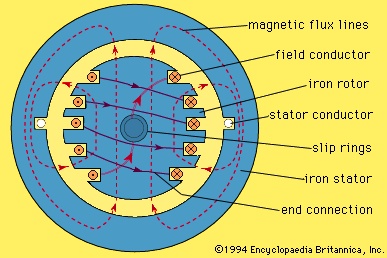 An elementary synchronous generator is shown in cross section in Figure 2-->. The central shaft of the rotor is coupled to the mechanical prime mover. The magnetic field is produced by conductors, or coils, wound into slots cut in the surface of the cylindrical iron rotor. This set of coils, connected in series, is thus known as the field winding. The position of the field coils is such that the outwardly directed or radial component of the magnetic field produced in the air gap to the stator is approximately sinusoidally distributed around the periphery of the rotor. In Figure 2-->, the field density in the air gap is maximum outward at the top, maximum inward at the bottom, and zero at the two sides, approximating a sinusoidal distribution.
Stator
The stator of the elementary generator in Figure 2--> consists of a cylindrical ring made of iron to provide an easy path for the magnetic flux. In this case, the stator contains only one coil, the two sides being accommodated in slots in the iron and the ends being connected together by curved conductors around the stator periphery. The coil normally consists of a number of turns.When the rotor is rotated, a voltage is induced in the stator coil. At any instant, the magnitude of the voltage is proportional to the rate at which the magnetic field encircled by the coil is changing with time—i.e.,the rate at which the magnetic field is passing the two sides of the coil. The voltage will therefore be maximum in one direction when the rotor has turned 90° from the position shown in Figure 2--> and will be maximum in the opposite direction 180° later. The waveform of the voltage will be approximately of the sine form shown in Figure 1-->. frequency
The rotor structure of the generator in Figure 2--> has two poles, one for magnetic (magnetic pole) flux directed outward and a corresponding one for flux directed inward. One complete sine wave is induced in the stator coil for each revolution of the rotor. The frequency of the electrical output, measured in hertz (cycles per second) is therefore equal to the rotor speed in revolutions per second. To provide a supply of electricity at 60 hertz, for example, the prime mover and rotor speed must be 60 revolutions per second, or 3,600 revolutions per minute. This is a convenient speed for many steam and gas turbines. For very large turbines, such a speed may be excessive for reasons of mechanical stress. In this case, the generator rotor is designed with four poles spaced at intervals of 90°. The voltage induced in a stator coil, which spans a similar angle of 90°, will consist of two complete sine waves per revolution. The required rotor speed for a frequency of 60 hertz is then 1,800 revolutions per minute. For lower speeds, such as are employed by most water turbines, a larger number of pole pairs can be used. The possible values of rotor speed, in revolutions per minute, are equal to 120 f/p, where f is the frequency and p the number of poles.Stator windings
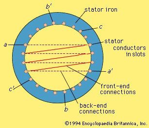 The maximum value of flux density in the air gap is limited by magnetic saturation in the stator and rotor iron, and is typically about one tesla (weber per square metre). The effective, or root-mean-square (rms), voltage induced in one turn of a stator coil in a 2-pole, 60-hertz generator is about 170 volts for each metre squared of area encompassed by the turn. Large synchronous generators are usually designed for a terminal voltage of several thousand volts. Each stator coil may therefore contain a number of insulated turns of conductor, and each stator winding usually consists of a number of similar coils placed in sequential slots in the stator surface and connected in series as shown for the winding a-a′ in Figure 3-->.
Phases (phase)
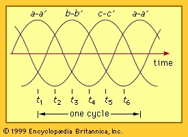 The voltages induced in individual coils in the distributed winding of Figure 3--> are somewhat displaced in time from each other. As a result, the maximum winding voltage is somewhat less than the voltage per coil multiplied by the number of coils. The waveform is, however, still of approximately sine form. In the figure the winding a-a′ spans two arcs, each of 60°. In order to make use of the whole periphery of the stator surface, two other similar windings are inserted. The voltage induced in winding b-b′ will be equal in peak magnitude to that of a-a′ but will be delayed in time by one-third of a cycle. The voltage in winding c-c′ will be delayed by an additional third of a cycle. This is known as a three-phase system of windings. The waveforms for the three windings, or phases, are shown in Figure 4-->.The three-phase arrangement has a number of advantages. A single winding, or phase, requires two conductors for transmission of its electrical power to a load. At first glance, it might appear that six conductors would be required for the system in Figure 3-->. If, however, the waveforms of Figure 4--> are considered to be those of the currents flowing in the three-phase windings, it will be seen that the sum of the three currents is zero at every instant in time. Thus, as long as the three phases are loaded equally, the terminals a′, b′, and c′ of Figure 3--> can be connected together to form a neutral point that may either be connected to ground or in some cases left open. The power of all three phases can be transmitted on three conductors. This connection is called a star, or wye, connection. Alternatively, since the three winding voltages also sum to zero at every instant, the three windings can be connected in series—a′ to b, b′ to c, and c′ to a—to form a delta connection. The output can then be transmitted using only three conductors connected to the three junction points. Other advantages of the three-phase system will become evident in the discussion of electric motors below.
Field excitation
A source of direct current is required for the field winding, as sketched in Figure 2-->. In very small synchronous generators, this current may be supplied from an external source by fitting the generator shaft with two insulated copper (or slip) rings, connecting the field coil ends to the rings and providing a connection to the external source through fixed carbon brushes bearing on the rings.The power required for the field winding is that which is dissipated as heat in the winding resistance. In large generators, this is usually less than 1 percent of the generator rating, but in a generator with a capacity of 1,000 megavolt-amperes this will still be several megawatts. For most large synchronous generators, the field current is provided by another generator, known as an exciter, mounted on the same shaft. This may be a direct-current generator. In most modern installations, a synchronous generator is used as the exciter. For this purpose, the field windings of the exciter are placed on its stator and the phase windings on its rotor. A rectifier mounted on the rotating shaft is used to convert the alternating current to direct current. The field current of the main generator can then be adjusted by controlling the field current of the exciter.
Generator rating
The capacity of a synchronous generator is equal to the product of the voltage per phase, the current per phase, and the number of phases. It is normally stated in megavolt-amperes (MVA) for large generators or kilovolt-amperes (kVA) for small generators. Both the voltage and the current are the effective, or rms, values (equal to the peak value divided by √2).
The voltage rating of the generator is normally stated as the operating voltage between two of its three terminals—i.e., the phase-to-phase voltage. For a winding connected in delta, this is equal to the phase-winding voltage. For a winding connected in wye, it is equal to √3 times the phase-winding voltage.
The capacity rating of the machine differs from its shaft power because of two factors—namely, the power factor and the efficiency. The power factor is the ratio of the real power delivered to the electrical load divided by the total voltage–current product for all phases. The efficiency is the ratio of the electrical power output to the mechanical power input. The difference between these two power values is the power loss consisting of losses in the magnetic iron due to the changing flux, losses in the resistance of the stator and rotor conductors, and losses from the windage and bearing friction. In large synchronous generators, these losses are generally less than 5 percent of the capacity rating. These losses must be removed from the generator by a cooling system to maintain the temperature within the limit imposed by the insulation of the windings.
High-speed synchronous generators
Generators driven by high-speed steam turbines are almost always constructed with horizontal shafts. The rotor diameter is usually limited to a maximum of about one metre because of the high centrifugal forces produced. The length of the rotor may be several metres. The rotor shaft and the field structure are made of a solid alloy steel forging in which slots are machined to accept the field coils, as shown in Figure 2-->. These coils are insulated typically with mica and glass laminate. The coils are held in place by nonmagnetic wedges in the tops of the slots.The stator provides a path for the continuously varying magnetic flux. The stator core is therefore constructed of thin sheets, or laminations, of magnetic steel. The steel, being an electrical conductor, would tend to short-circuit the voltage induced in it if it were solid. Lamination breaks up the conducting path along the stator length and keeps the power losses in the stator steel at an acceptable value. Slots are punched around the inside periphery of the laminations to accommodate the stator coils. In large generators, each stator coil normally contains only one turn.
High-speed generators are enclosed within a closed cylindrical stator housing that extends between the bearings at the two ends. They are cooled by hydrogen gas circulating within the housing and also frequently through ducts within the stator conductors. Very large generators are cooled by circulating water through the stator and rotor conductors.
The ratings of synchronous generators for large power systems extend up to about 2,000 megavolt-amperes. Smaller power systems use generators of lower rating (e.g., 50 megavolt-amperes and up) since it is usually not desirable to have more than 10 percent of the total required system generation in one machine.
Waterwheel generators
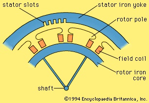 Hydraulic turbines are of various types, the choice depending largely on the height of water fall and on the power rating. The range of speed for which hydraulic turbines give acceptable efficiency is much lower than for steam turbines. The rotational speed is generally in the range of 60 to 720 revolutions per minute. The construction of low-speed synchronous generators is substantially different from that of high-speed units. To produce power at 60 hertz, the number of rotor poles is in the range of 10 to 120 for the above speed range. For these machines the rotor poles are of the projecting, or salient, type. Figure 5--> shows two poles of a 12-pole generator. Each pole, made of laminated magnetic steel, is encircled by a field coil. The pole is shaped so as to make the air-gap magnetic field distribution approximately sinusoidal.
Large hydraulic generators may have individual ratings in excess of 200 megavolt-amperes. They are mounted with a vertical shaft directly coupled to the turbine. The combination is usually supported on a single bearing, either above or below. The diameter is made relatively large to obtain a high peripheral velocity at low rotational speeds. The axial length of the generator is relatively short. The windings are frequently water-cooled. The rotor has to be designed to withstand a considerable overspeed condition that may arise if the generator loses its electrical load and there is a significant time delay in cutting off the water flow to the turbine.
Generators for motor vehicles
Vehicles such as automobiles, buses, and trucks require a direct-voltage supply for ignition, lights, fans, and so forth. In modern vehicles the electric power is generated by an alternator mechanically coupled to the engine. The alternator normally has a rotor field coil supplied with current through slip rings. The stator is fitted with a three-phase winding. A rectifier is used to convert the power from alternating to direct form. A regulator is used to control the field current so that the output voltage of the alternator-rectifier is properly matched to the battery voltage as the speed of the engine varies.
Permanent-magnet generators
For some applications, the magnetic field of the generator may be provided by permanent magnets. The rotor structure can consist of a ring of magnetic iron with magnets mounted on its surface. A magnet material such as neodymium-boron-iron or samarium-cobalt can provide a magnetic flux density in the air gap comparable to that produced with field windings, using a radial depth of magnet of less than 10 millimetres. Other magnet materials such as ferrite can be used, but with a considerable reduction in air-gap flux density and a corresponding increase in generator dimensions.
Permanent-magnet generators are simple in that they require no system for the provision of field current. They are highly reliable. They do not, however, contain any means for controlling the output voltage. A typical example of use is with a wind turbine where the generator output of variable voltage and frequency is supplied to a power system through an electronic frequency converter.
Induction generators
An induction machine can operate as a generator if it is connected to an electric supply network operating at a substantially constant voltage and frequency. If torque is applied to the induction machine by a prime mover, it will tend to rotate somewhat faster than its synchronous speed, which is equal to 120 f/p revolutions per minute, where f is the supply frequency and p is the number of poles in the machine. The rotor conductors, moving faster than the air-gap field, will have induced currents that interact with the magnetic field to produce a torque with which to balance that applied by the prime mover. A stator current will then flow into the supply network delivering electrical power. The amount of power delivered is approximately proportional to the difference between the rotor speed and the field speed. This difference is typically of the order of 0.5 to 2 percent of rated speed at rated load.
An induction generator cannot normally provide an independent electrical power source because it does not contain a source of its own magnetic field. Stand-alone induction generators can, however, operate with the aid of appropriate loading capacitors.
Induction generators are frequently preferred over synchronous generators for small hydroelectric sites because they are not subject to loss of synchronism following transient changes in the power system.
Inductor alternators
An inductor alternator is a special kind of synchronous generator in which both the field and the output winding are on the stator. In the homopolar type of machine, the magnetic flux is produced by direct current in a stationary field coil concentric with the shaft. In the heteropolar type, the field coils are in slots in the stator.
Voltage is generated in the output windings by pulsations in the flux in individual stator teeth. These pulsations are produced by use of a toothed rotor, which causes the reluctance of the air path from the rotor to each stator tooth to vary periodically with rotation.
Inductor alternators are useful as high-frequency generators. They also are useful in situations requiring high reliability, a feature achieved by their having no electrical connections to the rotor.
Direct-current generators
A direct-current (DC) generator is a rotating machine that supplies an electrical output with unidirectional voltage and current. The basic principles of operation are the same as those for synchronous generators. Voltage is induced in coils by the rate of change of the magnetic field through the coils as the machine rotates. This induced voltage is inherently alternating in form since the coil flux increases and then decreases, with a zero average value.
The field is produced by direct current in field coils or by permanent magnets on the stator. The output, or armature, windings are placed in slots in the cylindrical iron rotor. A simplified machine with only one rotor coil is shown in Figure 6. The rotor is fitted with a mechanical rotating switch, or commutator, that connects the rotor coil to the stationary output terminals through carbon brushes. This commutator reverses the connections at the two instants in each rotation when the rate of change of flux in the coil is zero—i.e., when the enclosed flux is maximum (positive) or minimum (negative). The output voltage is then unidirectional but is pulsating for the simple case of one rotor coil. In practical 2-pole machines, the rotor contains many coils symmetrically arranged in slots around the periphery and all connected in series. Each coil is connected to a segment on a multi-bar commutator. In this way, the output voltage consists of the sum of the induced voltages in a number of individual coils displaced around half the periphery. The magnitude of the output voltage is then approximately constant, containing only a small ripple. The voltage magnitude is proportional to the rotor speed and the magnetic flux. Control of output voltage is normally provided by control of the direct current in the field.
For convenience in design, direct-current generators are usually constructed with four to eight field poles, partly to shorten the end connections on the rotor coils and partly to reduce the amount of magnetic iron needed in the stator. The number of stationary brushes bearing on the rotating commutator is usually equal to the number of poles but may be only two in some designs.
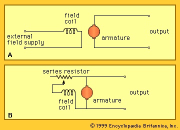 The field current for the generator may be obtained from an external source, such as a battery or a rectifier, as shown in Figure 7A-->. In this case, the generator is classed as separately excited. Alternatively, it may be noted that the output of the DC generator is unidirectional and therefore may be used as a source to supply its own field current, as shown in Figure 7B-->. In this case, the generator is referred to as shunt-excited. It has the advantage of requiring no independent electrical supply. Residual magnetic flux in the iron poles produces a small generated voltage as the machine is brought up to speed. This causes a field current that increases the flux and in turn the generated voltage. The voltage builds up until saturation in the iron limits the voltage produced. The stable value of generated voltage can be adjusted over a limited range by adjusting the value of a resistor placed in series with the field coil.
Direct-current generators were widely used prior to the availability of economical rectifier systems supplied by alternators. For example, they were commonly employed for charging batteries and for electrolytic systems. In some applications, the direct-current generator retains an advantage over the alternator-rectifier in that it can operate as a motor as well, reversing the direction of power flow. An alternator, by contrast, must be fitted with a more complex rectifier-inverter system to accomplish power reversal.
Additional Reading
Overviews may be found in the following texts: Gordon R. Slemon, Electric Machines and Drives (1992); Syed A. Nasar (ed.), Handbook of Electric Machines (1987); Syed A. Nasar and L.E. Unnewehr, Electromechanics and Electric Machines, 2nd ed. (1983); Vincent Del Toro, Electric Machines and Power Systems (1985); and George McPherson and Robert D. Laramore, An Introduction to Electrical Machines and Transformers, 2nd ed. (1990).
- Richard Le Grant
- Richard Lemon Lander
- Richard Lepsius
- Richard Lester
- Richard Lippold
- Richard Llewellyn
- Richard Lovelace
- Richard Lovell Edgeworth
- Richard Mansfield
- Richard March Hoe
- Richard Mather
- Richard M. Daley
- Richard Mead
- Richard Meier
- Richard Milhous Nixon: First Inaugural Address
- Richard Milhous Nixon: Second Inaugural Address
- Richard M Johnson
- Richard M. Nixon
- Richard M. Nixon: Resignation from the Presidency
- Richard Monckton Milnes
- Richard Montagu
- Richard Morris Hunt
- Richard Mortensen
- Richard Mulcaster
- Richard N. Barton