jet engine
engineering
Introduction
any of a class of internal-combustion engines that propel aircraft by means of the rearward discharge of a jet of fluid, usually hot exhaust gases generated by burning fuel with air drawn in from the atmosphere.
General characteristics
The prime mover of virtually all jet engines is a gas turbine. Variously called the core, gas producer, gasifier, or gas generator, the gas turbine converts the energy derived from the combustion of a liquid hydrocarbon fuel to mechanical energy in the form of a high-pressure, high-temperature airstream. This energy is then harnessed by what is termed the propulsor (e.g., airplane propeller and helicopter rotor) to generate a thrust with which to propel the aircraft.
Principles of operation
The prime mover
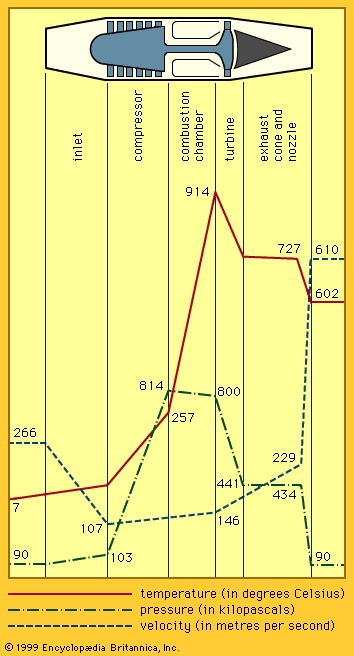 The gas turbine operates on the Brayton cycle in which the working fluid is a continuous flow of air ingested into the engine's inlet. The air is first compressed by a turbocompressor to a pressure ratio of typically 10 to 40 times the pressure of the inlet airstream (as shown in Figure 1-->). It then flows into a combustion chamber, where a steady stream of the hydrocarbon fuel, in the form of liquid spray droplets and vapour or both, is introduced and burned at approximately constant pressure. This gives rise to a continuous stream of high-pressure combustion products whose average temperature is typically from 980 to 1,540 °C or higher. This stream of gases flows through a turbine, which is linked by a torque shaft to the compressor and which extracts energy from the gas stream to drive the compressor. Because heat has been added to the working fluid at high pressure, the gas stream that exits from the gas generator after having been expanded through the turbine contains a considerable amount of surplus energy—i.e., gas horsepower—by virtue of its high pressure, high temperature, and high velocity, which may be harnessed for propulsion purposes.
The heat released by burning a typical jet fuel in air is approximately 43,370 kilojoules per kilogram (18,650 British thermal units per pound) of fuel. If this process were 100 percent efficient, it would then produce a gas power for every unit of fuel flow of 7.45 horsepower/(pounds per hour), or 12 kilowatts/(kg per hour). In actual fact, certain practical thermodynamic limitations, which are a function of the peak gas temperature achieved in the cycle, restrict the efficiency of the process to about 40 percent of this ideal value. The peak pressure achieved in the cycle also affects the efficiency of energy generation. This implies that the lower limit of specific fuel consumption (SFC) for an engine producing gas horsepower is 0.336 (pound per hour)/horsepower, or 0.207 (kg per hour)/kilowatt. In actual practice, the SFC is even higher than this lower limit because of inefficiencies, losses, and leakages in the individual components of the prime mover.
Because weight and volume are at a premium in the overall design of an aircraft and because the power plant represents a large fraction of any aircraft's total weight and volume, these parameters must be minimized in the engine design. The airflow that passes through an engine is a representative measure of the engine's cross-sectional area and hence its weight and volume. Therefore, an important figure of merit for the prime mover is its specific power—the amount of power that it generates per unit of airflow. This quantity is a very strong function of the peak gas temperature in the core at the discharge of the combustion chamber. Modern engines generate from 150 to 250 horsepower/(pound per second), or 247 to 411 kilowatts/(kg per second).
The propulsor
The gas horsepower generated by the prime mover in the form of hot, high-pressure gas is used to drive the propulsor, enabling it to generate thrust for propelling or lifting the aircraft. The principle on which such a thrust is produced is based on Newton's second law of motion. This law generalizes the observation that the force (F) required to accelerate a discrete mass (m) is proportional to the product of that mass and the acceleration (a). In effect,
where the mass is taken as the weight (w) of the object divided by the acceleration due to gravity (g) at the place where the object was weighed. In the case of a jet engine, one is generally dealing with the acceleration of a steady stream of air rather than with a discrete mass. Here, the equivalent statement of the second law of motion is that the force (F) required to increase the velocity of a stream of fluid is proportional to the product of the rate of mass flow (M) of the stream and the change in velocity of the stream,
where the inlet velocity (V0) relative to the engine is taken to be the flight velocity and the discharge velocity (Vj) is the exhaust or jet velocity relative to the engine. W is the rate of weight flow of working fluid (i.e., air or products of combustion) divided by the acceleration of gravity in the place where the weight flow is measured. The relatively small effect of the weight flow of fuel in creating a difference between the weight flow of the inlet and exhaust streams is intentionally disregarded.
One thereby infers that the components of a propulsor must exert a force F on the stream of air flowing through the propulsor if this device accelerates the airstream from the flight velocity V0 to the discharge velocity Vj. The reaction to that force F is ultimately transmitted by the mounts of the propulsor to the aircraft as propulsive thrust.
There are two general approaches to converting gas horsepower to propulsive thrust. In one, a second turbine (i.e., a low-pressure, or power, turbine) may be introduced into the engine flow path to extract additional mechanical power from the available gas horsepower. This mechanical power may then be used to drive an external propulsor, such as an airplane propeller or helicopter rotor. In this case, the thrust is developed in the propulsor as it energizes and accelerates the airflow through the propulsor—i.e., an airstream separate from that flowing through the prime mover.
In the second approach, the high-energy stream delivered by the prime mover may be fed directly to a jet nozzle, which accelerates the gas stream to a very high velocity as it leaves the engine, as is typified by the turbojet. In this case, the thrust is developed in the components of the prime mover as they energize the gas stream.
In other types of engines, such as the turbofan, thrust is generated by both approaches: A major part of the thrust is derived from the fan, which is powered by a low-pressure turbine and which energizes and accelerates the bypass stream (see below). The remaining part of the total thrust is derived from the core stream, which is exhausted through a jet nozzle.
Just as the prime mover is an imperfect device for converting the heat of fuel combustion to gas horsepower, so the propulsor is an imperfect device for converting the gas horsepower to propulsive thrust. There is generally a great deal of energy left in the high-temperature, high-velocity jet stream exiting from the propulsor that is not fully exploited for propulsion. The efficiency of a propulsor, propulsive efficiency ηp, is the portion of the available energy that is usefully applied in propelling the aircraft compared to the total energy of the jet stream. For the simple but representative case of the discharge airflow equal to the inlet gas flow, it is found that
Although the jet velocity Vj must be larger than the aircraft velocity V0 to generate useful thrust, a large jet velocity that exceeds flight speed by a substantial margin can be very detrimental to propulsive efficiency. Maximum propulsive efficiency is approached when the jet velocity is almost equal to (but, of necessity, slightly higher than) the flight speed. This fundamental fact has given rise to a large variety of jet engines, each designed to generate a specific range of jet velocities that matches the range of flight speeds of the aircraft that it is supposed to power.
The net assessment of the efficiency of a jet engine is the measurement of its rate of fuel consumption per unit of thrust generated (e.g., in terms of pounds, or kilograms, per hour of fuel consumed per pounds, or kilograms, of thrust generated). There is no simple generalization of the value of specific fuel consumption of a thrust engine. It is not only a strong function of the prime mover's efficiency (and hence its pressure ratio and peak-cycle temperature) but also of the propulsive efficiency of the propulsor (and hence of the engine type). It also is a strong function of the aircraft flight speed and the ambient temperature (which is in turn a strong function of altitude, season, and latitude).
Basic engine types
Achieving a high propulsive efficiency for a jet engine is dependent on designing it so that the exiting jet velocity is not greatly in excess of the flight speed. At the same time, the amount of thrust generated is proportional to that very same velocity excess that must be minimized. This set of restrictive requirements has led to the evolution of a large number of specialized variations of the basic turbojet engine, each tailored to achieve a balance of good fuel efficiency, low weight, and compact size for duty in some band of the flight speed–altitude–mission spectrum. There are two major general features characteristic of all the different engine types, however. First, in order to achieve a high propulsive efficiency, the jet velocity, or the velocity of the gas stream exiting the propulsor, is matched to the flight speed of the aircraft—slow aircraft have engines with low jet velocities and fast aircraft have engines with high jet velocities. Second, as a result of designing the jet velocity to match the flight speed, the size of the propulsor varies inversely with the flight speed of the aircraft—slow aircraft have very large propulsors, as, for example, the helicopter rotor—and the relative size of the propulsor decreases with increasing design flight speed—turboprop propellers are relatively small and turbofan fans even smaller.
Although the turbojet is the simplest jet engine and was invented and flown first among all the engine types, it seems useful to examine the entire spectrum of engines in the order of the flight-speed band in which they serve, starting with the slowest—namely, the turboshaft engine, which powers helicopters (helicopter).
Turboshaft engines
 The helicopter is designed to operate for substantial periods of time hovering at zero flight speed. Even in forward flight, helicopters rarely exceed 240 kilometres per hour or a Mach number of 0.22. (The Mach number is the ratio of the velocity of the aircraft to the speed of sound.) The principal propulsor is the helicopter rotor, which is driven by one or more turboshaft engines (see Figure 2-->) in all modern helicopters of large size. As was previously noted, the propulsor is designed to give a very low discharge or jet velocity and is by the same token very large for a given size aircraft when compared to the propulsors of higher-speed aircraft. The prime mover of a helicopter is a core engine whose gas horsepower is extracted by a power turbine, which then drives the helicopter rotor via a speed-reducing (and combining) gearbox. The power turbine is usually located on a spool separate from the gas generator; thus its rotative speed and that of the helicopter rotor which it drives are independent of the rotative speed of the gas generator. This allows the rotor speed to be varied or kept constant independently of the gas-generator speed, which must be varied to modulate the amount of power generated.
Turboprops (turboprop), propfans, and unducted fan engines
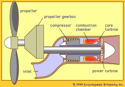 The turboprop is the power plant that occupies the next band of flight speeds in the flight spectrum, from a Mach number of 0.2 to 0.7. The propulsor is a propeller with a somewhat higher discharge, or jet velocity, than that of the helicopter rotor to match the flight speed, and it has a proportionately smaller area than the latter for a similarly sized aircraft. The prime mover is a turboshaft engine (very similar to the one that drives a helicopter rotor except for a different gearbox; see Figure 3-->) designed to provide a somewhat higher rotative speed for the propeller, which turns faster than the helicopter rotor having a much larger diameter. The control mode of the turboprop also is somewhat different from that of a helicopter's turboshaft engine. In a helicopter the pilot calls for power by manipulating the pitch of the rotor blades (a greater pitch taking a bigger “bite” of air and so demanding more power to maintain rotative speed). The engine's control responds by increasing fuel to the engine to maintain output shaft speed. In a turboprop the pilot calls for power by selecting fuel flow to the prime mover. The propeller control responds by varying propeller pitch to attain a greater “pull” while maintaining a preselected propeller rotative speed.
A recent trend in turboprop design has been the evolution of propellers for efficient operation at transonic flight speeds (those approximating the speed of sound), much higher than previously achieved—up to Mach numbers of 0.85. This usually involves a higher disk loading (i.e., a higher discharge velocity from the propeller) in order to permit the use of a smaller diameter propeller. This trend has been accompanied by an increase in the number of blades in the propeller (from 6 to 12 instead of the more common 2 to 4 blades in lower-speed propellers). The blades are scimitar-shaped, with swept-back leading edges at the blade tips to accommodate the large Mach numbers encountered by the propeller tip at high rotative and flight speeds. Such high-speed propulsors are called propfans.
Another variation of the propulsor involves the application of two concentric propellers on the same centreline, driven by the same prime mover through a gearbox that causes each propeller to rotate in a direction opposite the other. Such counter-rotating propellers are capable of significantly higher propulsive efficiency and higher disk loading than conventional propellers.
In most turboprop installations the prime mover is mounted on the wing, and the plane of the propeller is forward of the prime mover (the so-called tractor layout). Modern high-speed aircraft may find it more advantageous to mount the engine more toward the rear of the aircraft, with the plane of the propeller aft of the engine. These arrangements are referred to as “pusher” layouts. A recently developed engine layout, identified as the unducted fan (or UDF; trademark), provides a set of very high-efficiency counter-rotating propeller blades, each blade mounted on one of either of two sets of counter-rotating low-pressure turbine stages and achieving all the advantages of the arrangement without the use of a gearbox.
Medium-bypass turbofans, high-bypass turbofans, and ultrahigh-bypass engines
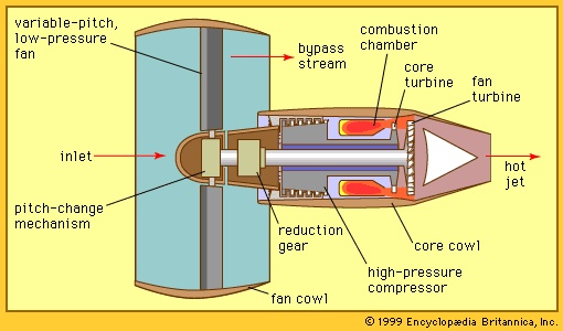
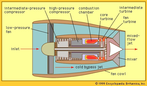 Moving up in the spectrum of flight speeds to the transonic regime—Mach numbers from 0.75 to 0.9—the most common engine configurations are turbofan engines, such as those shown in Figures 4--> and 5-->. In a turbofan, only a part of the gas horsepower generated by the core is extracted to drive a propulsor, which usually consists of a single low-pressure-ratio, shrouded turbocompression stage. The fan is generally placed in front of the core inlet so that the air entering the core first passes through the fan and is partially compressed by it. Most of the air, however, bypasses the core (hence the designation bypass stream) and goes directly to an exhaust nozzle. The core stream, with some modest fraction of the gas horsepower remaining (not extracted to drive the fan) proceeds directly to its own exhaust nozzle.A key parameter for classifying the turbofan is its bypass ratio, defined as the ratio of the mass flow rate of the bypass stream to the mass flow rate entering the core. Since the highest propulsion efficiencies are obtained by the engines with the highest bypass ratios, one would expect to find all engines of that design in this flight speed regime. (Some of the variation derives from historical evolution.) In actuality, however, one finds engines with a broad spectrum of bypass ratios, including medium-bypass engines (with bypass ratios from 2 to 4), high-bypass engines (with bypass ratios from 5 to 8), and ultrahigh-bypass engines, so-called UBEs (with bypass ratios from 9 to 15 or higher). A whole generation of low- and medium-bypass engines has completely supplanted the first generation of aircraft powered by (zero-bypass) turbojet engines. Moreover, that generation was itself supplanted by a third generation of medium- and high-bypass turbofan engines. There are several other reasons why engines with less than the highest bypass ratios hypothetically achievable are still in use. Very high bypass ratios involve the use of fans with very large diameters, which in turn entail very heavy components; this increases the difficulty of installing the engine on aircraft and maintaining sufficient ground clearance. In addition, the weight and complexity of the apparatus required to reverse the direction of the bypass stream (to achieve thrust reversal in order to shorten the aircraft's landing roll) also increases with the bypass ratio. The long-term trend, however, is definitely toward higher and higher bypass ratios.There are several unique features and ancillary devices found in turbofan engines. Ultrahigh-bypass engines (as shown in Figure 4-->) may have a gearbox between the drive turbine and the fan to simplify the design of the small-diameter turbine (with the attendant high rotative speed) without compromising the performance of the very large-diameter fan (with the attendant low rotative speed). Variable-pitch fan blades are generally required for thrust reversal in such ultrahigh-bypass fans, while in medium- and high-bypass engines the thrust reversing is usually accomplished by introducing blocker doors into the bypass stream. In high- and medium-bypass turbofans (Figure 5-->), a small but significant improvement in propulsive efficiency can be achieved by mixing the airstream of the hot core and cold bypass streams before the total airstream enters a single jet nozzle.
Low-bypass turbofans and turbojets
In the next higher regime of aircraft flight speed, the low supersonic (supersonic flight) range from Mach numbers above 1 up to 2 or 3, one finds the application of the simple turbojet (with no bypass stream) and the low-bypass turbofan engine (with a bypass ratio up to 2).
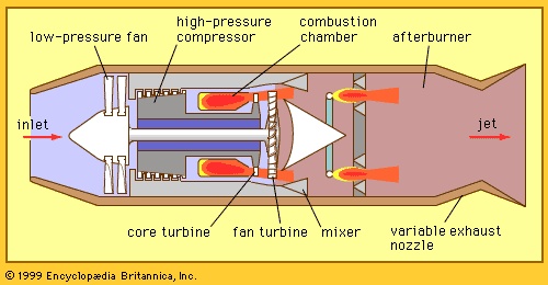 Although the low-bypass turbofan (shown in Figure 6-->) has the same general appearance as a turbofan with a larger bypass ratio, certain special features are unique to low-bypass engines. The lower total flow in the fan generally involves a higher fan pressure ratio (for equivalent amounts of energy available from the drive turbine), and so such a fan usually has more than one (i.e., two or three) turbocompressor stages. Engines designed to operate at the low supersonic range generally have insufficient thrust in other flight regimes or modes where they must operate for short durations, as, for instance, acceleration through transonic speed, takeoff from high-altitude airports under conditions of extremely high temperatures and high gross weight, or combat maneuvers at high supersonic flight speed. Rather than installing a larger engine to meet these requirements, it is more effective to add an afterburner to a turbofan engine as a means of thrust augmentation. The afterburner is a secondary combustion system that operates in the exhaust stream of the engine before the stream is introduced into the exhaust nozzle. Such a device is not as fuel-efficient as the main turbofan section of the engine because heat addition occurs at a lower pressure than in the main burner. The afterburner, however, is relatively simple and lightweight, since it does not contain any rotating machinery. For the same reason, it may be operated to a much higher discharge temperature (typically 1,760 °C), so that it is capable of augmenting the thrust of the turbofan by as much as 50 percent.The afterburner in a turbofan usually requires a mixer for mixing the relatively cool bypass air with the hot core stream (see Figure 6-->); the cooler air is otherwise difficult to burn in the low-pressure environment of an afterburner. Also, in both the turbojet and the turbofan with an afterburner, the exhaust nozzle must have a variable throat area to accommodate the large variations in volumetric flow rate between the very hot exhaust stream from the operating afterburner and the cooler airstream discharged from the engine when the afterburner is not in use. Engines intended for supersonic flight generally have a much lower compression-pressure ratio than higher-bypass machines intended for subsonic or transonic operation. A major contributor to this tendency is the additional pressure ratio developed in the engine's inlet as it slows down or diffuses the very high-speed airstream that is ingested as the engine's working fluid—the ram effect. At transonic flight speed this pressure ratio is almost 2:1, so that the engine's compressor may be built to provide that much less pressure where peak pressure is otherwise limiting.
Early generations of jet-propelled aircraft in this low supersonic flight regime were powered by turbojet engines, but subsequent generations built for the same flight regime have largely been equipped with low-bypass turbofans. This substitution of engine type was undertaken primarily because such aircraft expend a great deal of their fuel at subsonic flight speed (e.g., in takeoff, climb, loiter, acceleration, approach, and landing), where the turbofan provides an advantage in propulsive efficiency.
Ramjets (ramjet) and supersonic combustion ramjets
As has been seen, ram pressure plays an increasingly important role in the thermodynamic cycle of power and thrust generation of the jet engine at supersonic flight speeds. For flight speeds above Mach 2.5 or 3, the ram-pressure ratio becomes so high that a turbocompressor is no longer necessary for efficient thrust generation. Indeed, the pressure ratio eventually rises to such high values that the associated high ram temperatures make it difficult or impossible to place high-speed rotating machinery in the flow path without prohibitive amounts of cooling provision. This combination of circumstances gives rise to the ramjet, a jet engine in which the pressure increase is attributable only to the ram effect of the high flight speed; no turbomachinery is involved, and the main thrust producer is an afterburner.
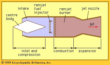 Ramjets (see Figure 7-->) are lightweight and simple power plants, making them ideal candidates for supersonic flight vehicles that are launched from other flight vehicles at extremely high speed. They are less suitable for use in vehicles that must be sufficiently self-powered for subsonic takeoff, climb, and acceleration to supersonic flight speed; the subsonic ram pressure is insufficient to produce any reasonable amount of thrust, and so alternative propulsion devices must be provided.
In the flight regime of Mach 4 or 5, it is usually efficient to decelerate the inlet airstream to subsonic velocity before it enters the combustion system. At still higher Mach numbers, such deceleration becomes more difficult and costly in terms of pressure losses, and it is necessary to make provision for the combustion chamber to burn its fuel in the supersonic airstream. Such specialized ramjets are called scramjets (for supersonic combustion ramjets) and are projected to be fueled by a cryogenically liquified gas (e.g., hydrogen or methane) instead of a liquid hydrocarbon. The primary reason for doing so is to exploit the greater heat release per unit weight of fuels that have a higher ratio of hydrogen to carbon atoms than ordinary fractions of petroleum even though this gain is partly negated by the higher volume per unit of heat release of those same fuels. Another incentive for employing a very cold fuel is that it may be used as a heat sink for cooling a very high-speed (and hence very hot) engine and aircraft structure. The scramjet has an unusual feature: the inlet deceleration and exhaust acceleration occur largely outside the enclosed engine inlet and exhaust ducts against external aircraft surfaces in front of and to the rear of the engine. In effect, the engine itself is little more than a sophisticated supersonic combustion chamber.
Hybrid engine types
It is possible to tailor an engine configuration so that the engine is well suited for operation within a given band of the flight spectrum. To have an engine that will perform well in more than one band of the flight spectrum or in more than one regime of operation, it may be necessary to configure the power plant so that it can be converted from one engine type to another by means of variable geometry built into the engine components.
Vertical and short takeoff and landing (V/STOL) propulsion systems
Propulsion systems that provide aircraft with the capability of both vertical and conventional forward flight represent a formidable challenge to the engine designer. V/STOL aircraft have several major categories of engine arrangement. They are as follows:
1. As in a helicopter, the propulsor may consist of a rotor that is driven by one or more turboshaft engines and is installed in such a way as to provide vertical thrust. The entire aircraft must be tilted to give the thrust vector a forward component to achieve forward flight. This arrangement has certain limitations in terms of effectiveness, as borne out by the relative inefficiency of forward flight above a Mach number of 0.2.
2. The propulsors may be mounted on pivots so that they can be rotated from the position in which they give vertical thrust in a takeoff, hover, climb, descent, or landing maneuver and pivoted 90° to provide thrust for conventional forward flight (as in the tilt-rotor aircraft). The prime mover that drives the propulsor may either be tilted with the propulsor or be fixed in the wing and drive the tilting propulsor via a rotating shaft through the pivot axis. In some configurations, the entire wing of the aircraft, carrying fixed engines and propulsors, may be tilted as a single assembly.
3. The engines may be fixed in a position required to produce thrust for forward flight. Their exhaust systems, however, have built-in variable geometry, making it possible to vector the exhaust nozzle (or nozzles) or divert the exhaust gases by means of valves and auxiliary ducts to nozzles mounted in such a way as to provide vertical thrust or lift.
4. The aircraft may include two different sets of engines or propulsors (or both), fixed in position, with one set installed for forward flight and the other for vertical thrust (i.e., the lift engines).
5. The aircraft may use a convertible engine. Such an engine has a single prime mover that is arranged to drive a fan for efficient forward propulsion, to drive a shaft that turns the main helicopter rotor, or to drive both a fan and a shaft. In order to convert from horizontal to vertical flight, variable-pitch fan blades or variable-pitch stators (or both) unload the fan, thereby making mechanical power available to drive the helicopter rotor for vertical movement.
Variable-cycle engines
For aircraft designed to fly mixed missions (i.e., at subsonic, transonic, and supersonic flight speeds) with low levels of fuel consumption, it is desirable to have an engine with the characteristics of both a high-bypass engine (for subsonic flight speed) and a low-bypass engine (for supersonic flight speed). This requirement is typical for many high-speed commercial airliners, including the Concorde, a type of supersonic transport built by the British and French that was in service from 1976 to 2003. The Concorde was capable of traveling over oceans and unpopulated land areas at supersonic cruise speeds, but it could not fly efficiently and quietly at subsonic flight speed for takeoff, ascent, cruising over populated areas, and approach and landing. This dual function is expected to be accomplished in the future by the variable-cycle engine (VCE). If the components of an engine are designed to accommodate the extreme limits of flow, pressure ratio, and other conditions involved in both high-bypass and low-bypass operation, the engine may be operated at either extreme of bypass ratio or at any bypass ratio between those extremes by means of a valve (or valves) in the bypass stream (in conjunction with a variable exhaust nozzle). When the valves are closed, they restrict the flow in the bypass stream to achieve low bypass for supersonic flight. When the valves are open, the bypass is increased to its maximum value for efficient subsonic flight.
Turboramjets
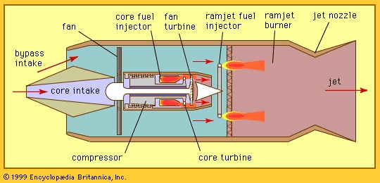 As noted above, the ramjet provides a simple and efficient means of propulsion for aircraft at relatively high supersonic flight speeds. It is, however, quite inefficient at transonic flight speeds and is completely ineffective at subsonic velocities. The turboramjet has been developed to overcome this inadequacy. In this system (shown in Figure 8-->), a turbofan engine is built into the inlet of a ramjet engine to charge the latter with a pressurized stream of air at subsonic flight speed where ram pressure is insufficient for effective ramjet operation. During supersonic flight the fan blades, if they are of variable pitch, may be feathered so that they do not interfere with the flow of ram air to the ramjet. A separate inlet to the core engine that drives the fan may be closed off so as not to expose the turbomachinery to the hostile environment of the high-temperature ram air.
Another variation of the turboramjet does without the core inlet and the core compressor altogether. Instead, the aircraft carries a tank of an oxidizer, such as liquid oxygen. The oxidizer is fed into the core combustion chamber along with the fuel to support the combustion process, which generates the hot gas stream to power the turbine that drives the fan. During supersonic flight, the fan may be feathered, and a surplus of fuel may be introduced into the core combustor. The unburned fuel passes through the fan turbine and undergoes combustion in the ramjet burner when it mixes with the fresh air entering via the bypass stream from the fan.
Development of jet engines
Like many other inventions, jet engines were envisaged long before they became a reality. The earliest proposals were based on adaptations of piston engines and were usually heavy and complicated. The first to incorporate a turbine design was conceived as early as 1921, and the essentials of the modern turbojet were contained in a patent in 1930 by Frank Whittle in England. His design was first tested in 1937 and achieved its first flight in May 1941. In Germany, parallel but completely independent work followed issuance of a patent in 1935. It proceeded more rapidly, and the very first flight of a turbojet-powered aircraft, a Heinkel HE-178, came in August 1939. By the end of World War II these prototype aircraft had developed into a few operational turbojet squadrons in the German, British, and U.S. air forces.
In the military (military aircraft) area, jet fighter aircraft developed rapidly and were in use during the Korean War (1950–53), flying at speeds of 1,000 km per hour. During the next decade they overcame the sound barrier and established normal operations up to more than twice the speed of sound (Mach 2). Bomber and transport jet aircraft were also able to reach and cruise at supersonic speeds.
The first civil jet transport, the British de Havilland Comet, flew in 1949, and regular transatlantic jet services were started in 1958 with the Comet 4 and the American Boeing 707. By 1974 more than 90 percent of hours flown throughout the world were flown by jets; the first supersonic airliner, the British-French Concorde, flying at more than twice the speed of sound, entered regular service in January 1976 and flew until late 2003.
During the 1980s various major aircraft manufacturers undertook programs to develop fuel-saving propfan and unducted-fan propulsion systems. Some authorities believe that the next generation of commercial air transport may very well be powered by such advanced-technology propeller engines.
Additional Reading
Texts on jet engines include two nontechnical works, Rolls-Royce Ltd., The Jet Engine, 4th ed. (1986), with a discussion of basic concepts and a systematic analysis of jet engine components; and Irwin E. Treager, Aircraft Gas Turbine Engine Technology, 2nd ed. (1979), with a section on the history of the jet engine. More technical treatments are found in Jack L. Kerrebrock, Aircraft Engines and Gas Turbines (1977), which deals primarily with the thermodynamic and aerodynamic operation of major engine components; and Gordon C. Oates, Aerothermodynamics of Gas Turbine and Rocket Propulsion, rev. and enlarged ed. (1988).