drafting
graphics
Introduction
also spelled draughting, also called engineering drawing
graphical representation of structures, machines, and their component parts that communicates the engineering intent of a technical design (industrial design) to the craftsman or worker who makes the product.
At the design stage, both freehand and mechanical drawings serve the functions of inspiring and guiding the designer and of communicating among the designer, collaborators, production department, and marketing or management personnel. At this stage exact mechanical drawings can clarify, confirm, or disqualify a scheme that looked promising in a freehand sketch. Actually, both the sketch and the exact mechanical drawing are essential parts of the process of designing, and both belong to the field of drafting. After the basic design has been established, drafting skills aid in the development and transmission of the wealth of data necessary for the production and assembly of the parts. For an automobile, a skyscraper, or a spacecraft, tens of thousands of drawings may be needed to convey all of the requirements of the finished product from the designers to the fabricators.
The completion of the set of drawings necessary for the manufacture of a product or the construction of a project involves three important factors: (1) itemization of every detail and requirement of the final product or project; (2) application of good judgment and knowledge of standard drafting procedures to select the combination of drawings and specifications that will convey the information identified in stage (1) in the clearest possible manner; and (3) deployment of skilled personnel and suitable equipment to produce the documents specified in stage (2).
Drafting is based on the concept of orthographic projection, which in turn is the principal concern of the branch of mathematics called descriptive geometry. Although preceded by the publication of related material and followed by an extensive development, the book Géométrie descriptive (1798) by Gaspard Monge (Monge, Gaspard, comte de Péluse), an 18th-century French mathematician, is regarded as the first exposition of descriptive geometry and the formalization of orthographic projection. The growth and development of the drafting profession were favoured by the application of the concepts published by Monge, the need to manufacture interchangeable parts, the introduction of the blueprinting process, and the economy offered by a set of drawings that in most cases made the building of a working model unnecessary.
Persons with a variety of skills and specialties are essential to the design and implementation of engineering and architectural projects. Drafting provides communication among them and coordination of their activities. The designer has primary responsibility for the basic conception and final solution but depends upon the support of several levels of drafters who prepare graphic studies of details; determine fits, clearances, and manufacturing feasibility; and prepare the working drawings. The delineator, or technical illustrator, converts preliminary or final drawings into pictorial representations, usually perspective constructions in full colour to help others visualize the product, to inform the public, to attract investment, or to promote sales. Before undertaking their own drawings, persons entering the profession of drafting may trace drawings to revise or repair them, then advance to the preparation of detail drawings, tables of materials, schedules of subassemblies (such as doors and windows), and the dimensioning of drawings initiated by more experienced colleagues. The wide spectrum of activities demanded of a design team requires that its members combine experience and creativity with skills in visualization, analysis, and delineation and with knowledge of materials, fabrication processes, and standards.
It is the responsibility of the manufacturing, fabricating, or construction workers to follow a set of drawings and specifications exactly; there should be no need for them to ask questions or make decisions regarding particulars of the design. All such particulars are the responsibility of the design team; the drawings must clearly convey all necessary information so that the functional requirements of and regulatory restrictions on the completed product or project are satisfied, the mechanical properties of the materials are appropriate, and the machining operations and assembly or erection procedures are possible.
The strictly utilitarian objectives of drafting and its emphasis on clarity and accuracy clearly differentiate it from the allied art form covered in the article drawing. Cartographic drafting is treated in the articles map and surveying. Some specific applications of drafting are dealt with in the articles building construction: Modern building practices (building construction); interior design; and clothing and footwear industry.
Types of drawings
Varying according to the product or project, the set of drawings (drawing) generally contains detail drawings (also called working drawings), assembly drawings, section drawings, plans (top views), and elevations (front views). For manufacturing a machine, the shape and size of each individual part, except standard fasteners, are described in a detail drawing, and at least one assembly drawing indicates how the parts fit together. To clarify interior details or the fitting together of parts, it may be necessary to prepare a section drawing, showing a part or assembly as though it had been cut by a plane, with a portion of the object removed. For constructing a building (building construction), plans, elevations, section drawings, and detail drawings are necessary to convey the information needed to estimate costs and then erect the structure. In this case the detail drawings contain exact information about such features as elevators, stairways, cabinetwork, and the framing of windows, doors, and spandrels. Different information appears in the set of drawings for a bridge, a dam, or a highway, but in each case the differences are related to the best manner of conveying the needed information.
Dimensions and tolerances
The sizes of parts and overall sizes of assemblies are conveyed by dimensions placed on the drawing. The basic objective in dimensioning (dimension) a drawing is to give the manufacturing or construction personnel the dimensions they need to do their work without requiring them to add, subtract, or estimate distances. If mass production is to be undertaken, special attention must be given to the dimensions of interchangeable parts that fit together. To dimension a distance as, say, two inches cannot require that it be exactly two (2.000 . . . ) inches, because no one can machine material with such precision. Particularly for parts of machinery, the designer must specify the acceptable range for the size of a hole, a shaft, or other feature requiring proper fit—perhaps 1.995 to 2.005 inches. The difference between the acceptable maximum and minimum dimensions given for a hole, shaft, or other feature is known as the tolerance. In the example above the tolerance is 0.010 (that is, 2.005 − 1.995) inch. Unsatisfactory tolerancy of mating parts ordinarily results in a machine with improper function or greatly reduced useful life. On the other hand, the cost of production increases greatly as tolerances are made stricter. It is an important design decision to require the correct level of tolerance for the functioning of any particular product. Additional information on a set of drawings indicates the materials to be used and the types of finish required on the surfaces.
Systems of representation
perspective
The shapes of all the parts and their interrelation are exactly described by the representation of that information in the set of drawings. Such description can be a lesser or greater challenge, depending on the complexity of the design. In the 15th century some of the leading artists and architects developed geometric schemes of perspective. Geometric perspective is a drawing method by which it is possible to depict a three-dimensional form as a two-dimensional image that closely resembles the scene as visualized by the human eye. The camera produces photographs (photography, history of) with such resemblance. Images produced by the eye, the camera, and systems of perspective can all be interpreted in terms of what is known as central projection. Lines of sight may be thought of as extending from the points of the object under observation to a central point of convergence—the lens of the eye or the camera, or the reference point of the perspective construction. In the case of the eye these lines of sight are focused by the lens into an image on the curved retina. In the camera they pass through the lens to form an image on a flat piece of film. In systems of geometric perspective the converging lines of sight form an image on an imaginary picture plane located between the object and the central point of the construction.
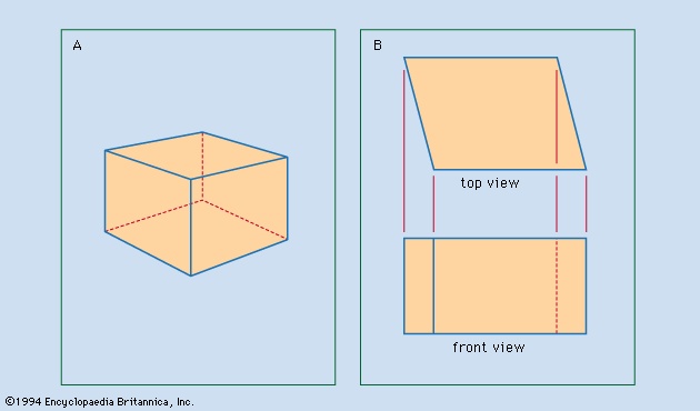 Perspective drawings and photographs are easily interpreted because they closely resemble visual images. This resemblance includes the diminution of the relative size of the representations of portions of the object that recede from the viewer and the distortion of the angular relations of the lines of the object. The object shown in perspective in Figure 1A--> may be interpreted as a cube. The same object is represented in Figure 1B--> according to the projectional system ordinarily used for engineering and architectural drawings; there it is evident that the object is not a cube. Such projections are used because they convey accurate information about the shape of the object.
Orthographic projection
The projection used for engineering and architectural (architecture) drawings is called orthogonal (orthographic projection) (“right-angled”) or orthographic because the lines of sight from points on the object to the picture plane of the image are perpendicular to that plane. Thus, the lines of sight, called projectors, are parallel rather than convergent (as they are in the central projection of the eye, the camera, and geometric perspective).
Descriptive geometry
 Monge's (Monge, Gaspard, comte de Péluse) reference system consisted of a vertical plane (V in Figure 2A--> ) and a horizontal plane (H) that intersected in a ground line. As in Figure 2A--> , Monge numbered the four quadrants formed by V and H I, II, III, and IV. Figure 2A--> also shows two arrows, D1 perpendicular to H and D2 perpendicular to V. Each arrow represents the direction of projection from points on any object under study to one of the reference planes. Such an object is the L-shaped block located in the first quadrant. Monge introduced the concepts of the reference system, the formation of views by projectors perpendicular to the reference planes, the revolving of the H plane into coincidence with the V plane about the ground line as indicated by the curved arrows, and the retention of the images on the planes after the object had been removed and the H plane revolved. Figure 2B--> illustrates the final result: the projection on V is regarded as the front view, and the projection on H as the top view.If the object were placed in the third quadrant (see Figures 2C and 2D--> ), the projections would be exactly the same, but their relative locations on the paper would be reversed. If the object were located in the second quadrant, the two projections would have the same shape and size as in Figures 2B and 2D--> . Depending on the location of the object in the second quadrant, however, now either projection might be located above the other or one projection might overlap the other. The same is the case if the object were located in the fourth quadrant. This uncertainty is the reason that commercial use is limited to first- or third-quadrant projection. First-quadrant projection is often referred to as first-angle projection, and third-quadrant projection as third-angle projection.
 Regardless of the quadrant (or angle) used, the views or projections are formed by the intersection of the projectors and the reference planes. Established conventions determine which points of the object are projected. If projectors were extended from every point on the object to the reference planes, the views would be silhouettes and would fail in their purpose of defining the object. The accepted rule is to project (1) all points on the edges between plane surfaces that bound the object and (2) all points at which the projectors forming the view are tangent to curved surfaces of the object. Figure 3--> illustrates these two sets of points. AB is the line of intersection of the cylindrical surface and plane surface ABCD. CB is the line of intersection of two plane surfaces. EF is not the line of intersection of two surfaces of the object, but projectors forming the top view are tangent to the cylindrical surface along the straight path from E to F, and thus EHFH properly appears in the top view. (The superscript H is used here to denote the projection on the H plane, and, similarly, V is used to denote the projection on the V plane.) CD is the line of intersection of the cylindrical surface and plane ABCD, but CHGH results from the tangency of projectors along the cylindrical surface. Every line projected in the identical front view of this object is a line of intersection of surfaces. AD, BC, and the plane ABCD all project as the same straight line in the front view because the plane ABCD is parallel to the projectors for that view.
 ambiguity
 Ambiguity must be avoided in the views, dimensions, and notes of a set of drawings. Figure 4A--> shows pictorial representations of three different objects for which the identical front and top views in Figure 4B--> are correct. The ambiguity in the shape description provided by front and top views alone can be eliminated by adding a third, or side, view obtained by projecting the object onto a vertical plane perpendicular to V. In Figure 4B--> each set of three views describes only one of the objects without ambiguity.
In commercial or industrial practice, sets of drawings ordinarily provide at least three views of any part that is not a stamping, a gasket, a flat wrench, or other essentially two-dimensional form. Depending on the shape of the part, there may be a left-side view, a right-side view, or both. There may be reason for a back view, a bottom view, or both. Additional views are discussed below.
Hidden lines
It is standard practice to use dashes to represent any line of an object that is hidden from view. A drafter—in deciding whether a line in a view should be represented as hidden or as visible—relies on the fact that in third-angle projection the near side of the object is near the adjacent view, but in first-angle projection the near side of the object is remote from the adjacent view. In Figure 4B--> (third-angle projection) the top of the front view is near the top view; the front of the top view is near the front view; and the front of the side view is near the front view. In first-angle projection, however, the top of the front view is remote from the top view; the front of the top view is remote from the front view, and the front of the side view is remote from the front view. In a third-angle projection, what is remote in an adjacent view cannot hide what is near in that view.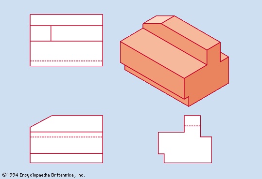 Figure 5--> shows a pictorial representation of an object and the third-angle projections of that object. The arrangement of the three views gives intuitive reinforcement to the correct selection of the line shown as hidden in each view because it is blocked by portions of the object that are nearer in the adjacent views. The number of hidden lines in a view of a complicated object may be very great. For purposes of studying visibility, the direction of projection may be thought of as always vertically downward for a top view, always horizontally from front to back for a front view, and always horizontally right-to-left for a right-side view.In Figure 5--> the hidden lines in the views could be identified by visualizing the object, a process that can be quite difficult for complicated objects. The following basic principle of descriptive geometry is useful in analyzing such a problem:
I. If any point is projected orthogonally onto each of two perpendicular planes and the planes are rotated into coincidence about their line of intersection, then the projections of the point on the two planes will lie on a straight line perpendicular to the line of intersection.
 Figure 6--> demonstrates this statement. Although the ground line, or line of intersection of H and V, is seldom drawn in the representations of front and top or of front, top, and side views of objects, it is understood to be horizontal. Thus for any point P, PH and PV lie on a vertical line of the drawing.
 A tetrahedron (triangular pyramid) with vertices A, B, C, and D is shown in third-angle projection in Figure 7--> . The edges AC and BD do not intersect, although their projections do. To determine which of these two edges is visible in the top view, the drafter considers location M, where the H projection of a point on AC and the H projection of a point on BD coincide. By principle I the V projections of these two points will lie on a vertical line from the crossing of AHCH and BHDH. A vertical construction line in Figure 7--> indicates that the point on BD is nearer to the top of the tetrahedron than the point on AC. This means that BD crosses above AC, so that BD must be visible in the top view and AC hidden. Similarly, to study the visibility of these lines in the front view, the vertical construction line is drawn through Q, the crossing of AVCV and BVDV; this procedure indicates that the point on BD is nearer to the front of the tetrahedron than the point on AC. Thus BD crosses in front of AC, so that BD is visible in the front view and AC is hidden.
Auxiliary views
 Figure 8--> illustrates another basic principle of descriptive geometry that facilitates the discussion of auxiliary views:
II. Given two planes (A and C) perpendicular to a third plane (B), a point P projected orthogonally onto the three planes, and the rotation of A and C into B about their respective lines of intersection with B (LA and LC), then PA is the same distance from LA as PC is from LC.
To convey complete and correct information many views may be necessary to show every plane surface bounding the object in its true size and shape at least once. In choosing the principal views, the drafter positions the object with reference to H and V so as to have the maximum number of its surfaces parallel to H or V or R, a third plane perpendicular to both H and V. Orthographic projection yields the true size and shape of every such surface in the front, the top, or the side view. A surface parallel to H or V or R, the three principal planes, is perpendicular to the other two. Additional or auxiliary views are necessary to represent the true size and shape of other plane surfaces. A plane perpendicular to only one of the three principal planes is said to be in an inclined position; a plane not perpendicular to any of the principal planes is said to be in an oblique position.
 Figure 9--> illustrates the application of principle II to represent the true size and shape of an inclined surface. The groove in surface ABCD makes an angle of 30° with a line (not shown) parallel to the edge DC. An auxiliary view in which A, B, C, and D are labeled with primes, obtained by projection onto a plane P, parallel to the surface ABCD, is the only one in which the true shape of ABCD and the true size of the 30° angle are correctly shown. The dimension indicated by the double-headed arrow is the same in the H (top) and auxiliary views, as required by principle II. The plane of the auxiliary view and the plane of the H view are perpendicular to the plane of the V view.
The true shape of an oblique surface can be shown correctly only on a second auxiliary view prepared by an extension of the procedure used for a first auxiliary view.
Automobile bodies, aircraft and ship hulls, and the irregular terrain of the natural site of a dam, bridge, or highway, are studied and detailed by means of contour lines on the surfaces. Three-dimensional modeling is necessary if design is highly competitive, as with automobiles, or if optimum streamlining is essential. Contour lines are projections of the intersections of the surface under study and imaginary planes at the reference locations.
Pictorial views
Although the emphasis on true descriptions of sizes and shapes requires orthographic projection for working and construction drawings, pictorial representations may be useful. In architecture, for example, the designer of the exterior of a building or the interior of an important space may be guided by perspective drawings and other pictorial representations. The construction of major projects may be preceded by the building of three-dimensional models, although these are expensive and seldom used in the early stages of design. Pictorial representations often are used for attracting investors or for advertising of new buildings and other products. Although a specialist in marketing might be intimidated by working drawings, he might grasp a pictorial representation easily enough to make useful suggestions about a design before production or construction was under way.
The execution of a perspective drawing may require more time than is justified in the design of a small item. In many cases orthographic projection, coupled with the rotation of the object with respect to the reference planes, produces an adequate pictorial representation.
Figures 2A, 2C-->, 3--> , 4A--> , and 5--> illustrate the pictorial representation achieved by oblique projection, in which the principal surface of the object is considered to be in the plane of the paper and thus is represented in true size and shape. The angle the receding axis makes with the horizontal lines of the drawing is chosen arbitrarily but with care in terms of the clarity of the particular representation. True lengths are set off along the receding axis as an arbitrary choice. This is a convenient method for constructing a pictorial representation. Unacceptable distortion results when oblique projection is used to represent large objects or those with large dimensions or important details along the receding axis.Drafting practice
Standards
The value of a set of drawings conveying the complete and correct information necessary for the execution of a project fostered the gradual standardization of practices. The widespread use of both first-angle and third-angle projection was long a major problem, but around the beginning of the 19th century a third-angle projection became the standard practice in the execution of industrial drawings in the United States. Australia followed this lead, but most industrial countries continued to follow Great Britain's use of first-angle projection. Architects in the United States and elsewhere generally use first-angle projection.
Drafting standards commonly evolve as a consensus develops among professional practitioners. Since 1917 in the United States the American National Standards Institute and its predecessors have encouraged this process and published standards for projections, various types of sections, dimensioning and tolerancing, representation of screw threads, all types of fasteners, graphic symbols for various specialties, and a great deal more. In other industrialized nations, analogous organizations—such as the British Standards Institution and the Deutsches Institut für Normung (“German Standards Institute”)—function in the same way. In addition, many industrial groups and individual companies have established more detailed standards for their particular purposes.
The International Organization for Standardization, with headquarters in Geneva, coordinates global standards. International communication is hindered by the lack of agreement concerning first-angle versus third-angle projection and by the persistence in the United States of inches, feet, and other customary units for dimensioning. Economic pressures, however, are moving American industries to adopt the international metric system, SI (International System of Units) units (Système Internationale d'Unités). The delay is related to the substantial costs of retooling and retraining. Because the strategy for correctly dimensioning a drawing is the same for all units, the rate of transition to SI units in the United States is not related to the drafting community, nor are SI units a special problem in drafting practice.
Equipment
Correct design information and projection are the imperatives of a set of engineering drawings. The skill and dexterity shown by some persons in drawing more accurately, more quickly, or more neatly have recognized value in the preparation of such drawings. Equipment has been invented to facilitate the performance of the manual tasks. Most widely known are the T square, triangle, protractor, and compass; the parallel straightedge is an alternative to the T square. The drafting machine, introduced about 1930, allows a straightedge to be moved while maintaining any desired angle between it and the edge of the drawing board. Combining the functions of the T square, triangle, protractor, and scale, it greatly increases the efficiency of producing a drawing.
Computers
A very important change in drafting procedure began in the early 1960s when programs were introduced to facilitate the composition of graphic images on the screen of a computer monitor, to retain the associated data in memory, and to retrieve the information to actuate plotting devices that produce not only the lines and arcs of an engineering drawing but also the symbols, dimension arrows, and strings of alphanumeric characters of notes and legends. Software can be prepared or purchased to perform the tasks involved in drafting: sketching of ideas to guide the design; calculation of the sizes of parts to satisfy codes, mechanical properties of materials, and machining requirements; preparation of working drawings; and production of pictorial representations. Computer-aided (computer-aided engineering) design (CAD) may be likened to word processing. Under direction, a word processor can correct misspellings, insert or delete words or sentences, rearrange sections of an article, or prepare accurately typed copies, but it cannot write an article. Similarly, knowledge, experience, and all but manual drawing skill are needed to produce a set of drawings with CAD, which has become increasingly important in industrial and architectural drafting.
Duplication of drawings
Blueprinting (blueprint), the first economical method for duplicating drawings, was invented in 1842 and introduced in the United States in 1876. The diazo process, xerography (electrophotography), and computer-controlled drafting machines have more recently shared this function. The availability of numerous copies of drawings facilitated the division of labour among artisans, who formerly had worked out many details—such as exact sizes and shapes of parts, fits, and clearances—while custom building each item. The specification of these details became the duty of the designer-drafters, requiring them to refine their skills accordingly and leading to further development of the drafting profession.
Additional Reading
Aspects of drafting from basic instruction to industrial practices are treated in Walter C. Brown, Drafting for Industry (1974, reprinted 1984), a comprehensive treatment including coverage of CAD; Paul Wallach, Metric Drafting (1979), with emphasis on the use of the international metric system for dimensioning and tolerancing; and Paul C. Barr et al., CAD: Principles and Applications (1985), which covers general-purpose CAD functions and applications to industrial practice and training. William T. Goodban and Jack J. Hayslett, Architectural Drawing and Planning, 3rd ed. (1979), discusses architectural sketching and drafting, including design concepts. See also George E. Rowbotham (ed.), Engineering and Industrial Graphics Handbook (1982).
- relative volumes occupied by some cellular compartments in a typical liver cell
- relativistic mass
- relativistic mechanics
- relativity
- relaxation phenomenon
- relaxin
- relay
- relay race
- R.E. Lee: Letter of Resignation
- Reles, Abe
- relic
- relief
- relief printing
- religion
- religion, philosophy of
- religions, classification of
- religion, study of
- Religious Adherents in the United States of America, 1900-2005
- Religious Adherents in the United States of America, 1900-2005 1
- Religious Adherents in the United States of America, 1900-2005 2
- Religious Adherents in the United States of America, 1900-2005 3
- Religious Adherents in the United States of America, 1900-2005 4
- Religious Adherents in the United States of America, 1900-2005 5
- Religious Adherents in the United States of America, AD 1900-2000
- Religious Adherents in the United States of America, AD 1900-2000 1